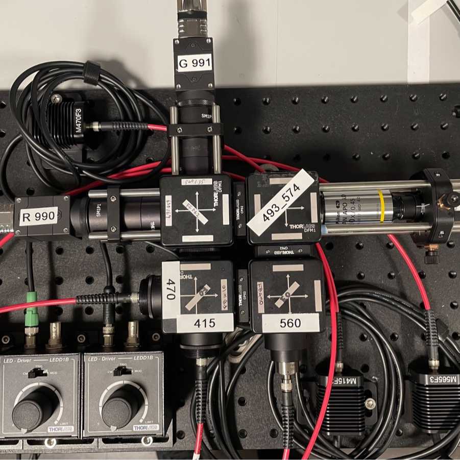
Mar 31, 2025
Modified Frame-projected Independent Fiber Photometry (FIP) System_Triggering system
- 1Allen Institute for Neural Dynamics
- Allen Institute for Neural Dynamics

Protocol Citation: Kenta M. Hagihara 2025. Modified Frame-projected Independent Fiber Photometry (FIP) System_Triggering system. protocols.io https://dx.doi.org/10.17504/protocols.io.kxygx3e6wg8j/v1
Manuscript citation:
Aggarwal, Abhi, Adrian Negrean, Yang Chen, Rishyashring Iyer, Daniel Reep, Anyi Liu, Anirudh Palutla, et al. “Glutamate Indicators with Increased Sensitivity and Tailored Deactivation Rates.” bioRxiv, March 24, 2025. https://doi.org/10.1101/2025.03.20.643984.
License: This is an open access protocol distributed under the terms of the Creative Commons Attribution License, which permits unrestricted use, distribution, and reproduction in any medium, provided the original author and source are credited
Protocol status: Working
We use this protocol and it's working
Created: July 06, 2023
Last Modified: March 31, 2025
Protocol Integer ID: 84608
Keywords: fiber photometry, calcium imaging, neuromodulator imaging, CMOS-based photometry
Abstract
Frame-projected independent fiber photometry (FIP) is a method to measure fluorescent sensor signals through optical fibers implanted in living animals, using a camera to record video of the fiber faces. To precisely control timings of excitation and camera frame acquisition for FIP, and of other external stimulation apparatus (e.g. LEDs for photo-stimulation), we use a Teensy 4.1 microcontroller, which generates voltage pulses without relying on continuous communication with the operating system of the experimental computer for timing. This protocol is for the 3 excitation LED + 2 collection CMOS cameras design.
Triggering-controlling software (an Arduino sketch) and data aquisition software (a Bonsai workflow) can be found in an associated github repository.
Guidelines
Teensy 4.1 only provides ~3.3V. If the device you want to trigger requires 5V (or more), the voltage needs to be up-regulated.
Materials
Equipment
Terminal Block Breakout Board Module for Teensy 4.1, Screw Mount Version
NAME
Breakout board
TYPE
OONO
BRAND
D-1395P
SKU
Software
Cables and connectors
USB2.0 cable (USB-A to Micro USB)
Jumper (or bare) wires
BNC cables
Miscellaneous
Solder (we used: Lead free wire from Amerway)
Soldering tools (we used: Weller WX2)
3D-printer (we used: Stratasys Dimension 1200es and IC3D Virago 700, with ABS and PETG filament, respectively)
A computer that can run Arduino/Teensy software. We used Windows 10 PCs but Max/Linux would work too.
Before start
Please see the accompanying protocol for the main FIP hardware design:
Protocol

NAME
Modified Frame-projected Independent Fiber Photometry (FIP) System_HardwareCREATED BY
Kenta M. Hagihara
Preparing an enclosure
Preparing an enclosure
As the Teensy 4.1 is a bare board, it should securely covered in an enclosure. The enclosure should be able to securely house Teensy 4.1, at least 5 BNC sockets, and optionally a small breadboard. Plastic 3D-printing (CAD design can be found here: 0294-100-01_X01.step246KB
  0294-100-02_X01.step3MB ) would be sufficient and could be any materials and designs.
Setting up an experimental PC and Teensy 4.1 device
Setting up an experimental PC and Teensy 4.1 device
25m
25m
10m
10m
Connect Teensy 4.1 device to the experimental PC using a USB cable, set proper COM port in the Arduino app, and upload the .ino sketch to the device. How to find and set up the corresponding COM port can be found here: https://support.arduino.cc/hc/en-us/articles/4406856349970-Select-board-and-port-in-Arduino-IDE.
5m
Connecting the Teensy 4.1 device to hardware to be controlled
Connecting the Teensy 4.1 device to hardware to be controlled
50m
50m
Place the Teensy 4.1 device on a breakout board (or a generic electric breadboard).
5m
Attach the breakout board and BNC(female) sockets to the enclosure.
10m
Solder wires between the breakout board and the BNC sockets according to this diagram for 3 excitation LEDs and 2 CMOS sensors configuration.
Fig1. Diagram for connections
Red wires (hot), green wires (ground)
30m
Connect the device to hardware (cameras and LEDs) to be controlled using BNC cables.
Protocol

NAME
Modified Frame-projected Independent Fiber Photometry (FIP) System_HardwareCREATED BY
Kenta M. Hagihara
All BNC ports connected to corresponding devices of the main hardware
10m
Software parameter setting
Software parameter setting
30m
30m
Based on acquisition frame rate and the CMOS cameras to be used, set the acquisition parameters in the .ino sketch.
Fig2. Scheme of temporal multiplexing of excitation and data acquisition
When acquisition is 60Hz (20Hz for each channel) with sufficiently fast CMOS sensors (e.g. FLIR, BFS-U3-20S4M-C), an example parameter set could be:
ExpT = 15650 μs
Δt1 = 666 μs
Δt2 = 300 μs
Δt3 = 50 μs
ExpT+ Δt1+Δt2+Δt3 = 16666 μs (= 1/60 s)
For better signal, Δt1/Δt2/Δt3 should be minimized to make the exposure time longer. If they are too short, however, the camera will not be able to unload the data (when Δt1 is too short) or LED instability at the onsets (when Δt2 is too short) would lead to periodic noise generation. Based on excitation light sources and CMOS models, optimize these parameters empirically.
30m
Protocol references
Kim, C., Yang, S., Pichamoorthy, N. et al. Simultaneous fast measurement of circuit dynamics at multiple sites across the mammalian brain. Nat Methods 13, 325–328 (2016). https://doi.org/10.1038/nmeth.3770
CAD design can be found here: 0294-100-01_X01.step246KB
  0294-100-02_X01.step3MB
Acknowledgements
We thank Joon Jung (Allen Institute, SIPE) for designing and 3D-printing the enclosure.
